If I had to start my career again, I would spend more time learning lighting and less time reading camera specifications. Many defects are already present in the image. The problem is that nobody can see them.
The real question is usually "How do we increase contrast?" - not "How do we increase resolution?"
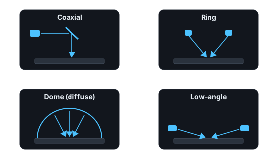
Coaxial lighting
Light travels down the optical axis via a beamsplitter, so flat mirror-like surfaces appear bright and anything tilted or scattering appears dark.
- Flat reflective surfaces, conductive traces, uniform illumination.
- Excellent for revealing reflectivity differences.
- Poor at revealing certain surface textures.
- Example: a 30 um dent on a polished pad is nearly invisible under a ring light but shows as a crisp dark spot under coaxial, because the dented surface no longer reflects straight back.
Ring lighting
The default starting point: directional enough to create some shadowing, diffuse enough to be forgiving.
- General-purpose, fast to set up, flexible, inexpensive.
- A great starting point.
- Watch for directional shadows and reflection artifacts.
- Example trap: a glossy conformal coating under a ring light produces a bright donut reflection that swamps everything underneath it. Tilting the part 5 degrees or switching to a dome usually solves it.
Dome lighting
Light arrives from nearly every direction at once, so surface angle stops mattering.
- Reflective parts and curved surfaces.
- Diffuse, even illumination that hides texture you do not want.
- Example: printed characters on a curved shiny cap are unreadable under any directional light; under a dome the glare disappears and the print is uniform.
- Remember the flip side: a dome hides scratches and dents just as effectively as it hides glare. Never use a dome when topography is the defect.
Low-angle (dark-field) lighting
Light grazes the surface at 10-30 degrees. Flat areas stay dark; edges, scratches and particles scatter light into the lens and glow.
- The go-to geometry for scratches, cracks, dust, and edge chips.
- Extremely sensitive - which means it also lights up harmless texture, so expect a false-call discussion.
UV lighting
- Organic contamination, coatings, fluorescent materials.
- Example: a fingerprint or flux residue that is invisible in white light fluoresces brightly at 365 nm.
IR lighting
- Material penetration and print suppression.
- Example: printed black text on a dark substrate disappears at 850 nm, letting you inspect the surface underneath the print.
How I run a lighting study
- Collect real defect samples and real good samples - not lab-made ones.
- Fix the camera and optic, then iterate lighting only. Change one variable at a time.
- For each geometry, capture the same defect and the same good region.
- Measure contrast as a number (defect mean minus background mean, divided by noise). Do not trust your eyes on a monitor.
- Pick the geometry with the best worst-case contrast across all defect samples, not the best single image.
A contrast of 10x the noise floor is comfortable. 3x is workable with care. Below 2x you are building a false-call machine.
The lesson
Many inspection problems are actually lighting problems. Solve the lighting and the algorithm often becomes trivial.